GPR Concrete Scanning Reveals Corrugated Metal Decking Bolts
Concrete Scanning to Locate Metal Roof Deck Fasteners or Bolts
Decking bolts, anchors, and connectors fasten corrugated metal decking to I-Beams. Since the placement of the decking bolts or fasteners, in part, determines the load bearing capacity of the concrete slab it is important to know how many fasteners there are and the distance between them. A building’s design incorporates the anticipated loads a floor or roof needs to handle. Thus, it may be necessary to confirm the placement of the corrugated metal decking bolts for proper use.
Updated 2017.
First, Locate the Lateral Support I-Beams
In order to locate the decking bolts using a concrete scanner, one needs to determine where to scan the concrete for the corrugated steel decking bolts. Since metal columns support the I-beams, one only needs to confirm which columns have lateral I-beams between them.
Second, Layout the GPR Survey Grid
Though it is easy to determine the location to scan, it takes thought to determine how large of an area to scan with the GPR and how far apart to place the grid lines. In other words, what is the grid line spacing? For decking bolts, which have a small head, it would not be wise to have lines too far apart. Lines one to two inches apart not only offer good coverage they may provide some redundancy that assists with providing greater resolution. For a large site with many locations to confirm, this could be a tedious task. Subsequently, it may be worth the effort to conduct a pilot GPR scan. For example, one could scan half of the distance between two columns, starting the grid at one column. Space the grid lines one inch apart in both directions.
After the GPR data is collected, process the data using multiple line spacings. During post processing, one can increase the spacing between grid lines by removing lines. In addition, one can observe the effect of removing either all of the lines parallel or perpendicular to the lateral I-beam. This process helps visualize the effects of line spacing and conditions within the slab (e.g. effects of wire mesh and reinforcing bars).
Review Site Conditions
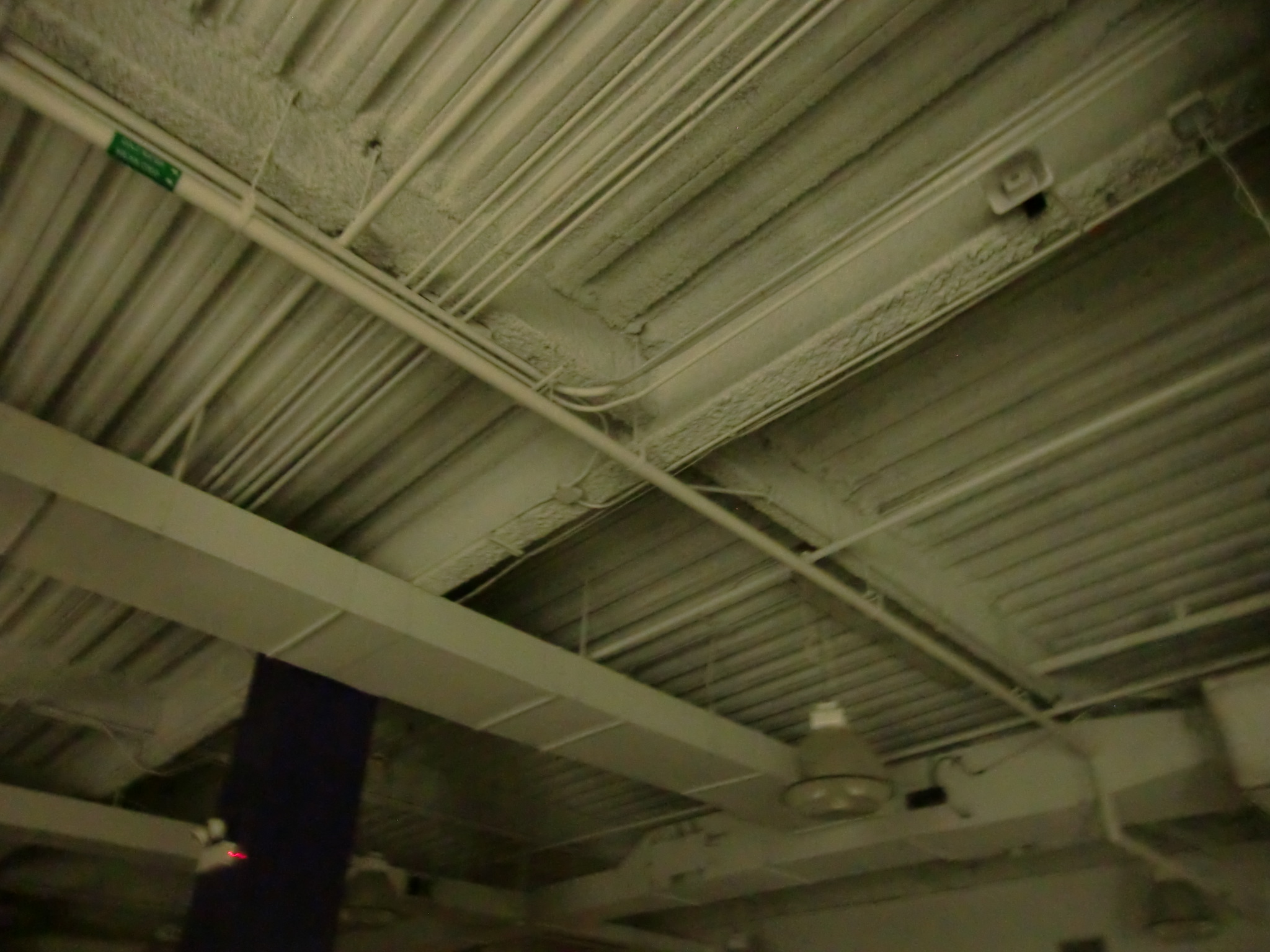
Wire mesh or closely spaced re-bar compounds the problem of mapping the decking bolts. Overlying metal or metal that is adjacent to the corrugated metal decking bolts may cause interference. While the decking bolts may respond well their response is hidden in the interference. At the same time, if the decking fasteners are below the peaks of the corrugated metal decking, imaging the fasteners may be challenging. Therefore, it is best if the decking bolts stick up well above the highest point of the decking. This is often the case for a concrete slab with a good engineering design.
GPR Concrete Scanning Reveals Corrugated Decking Bolts
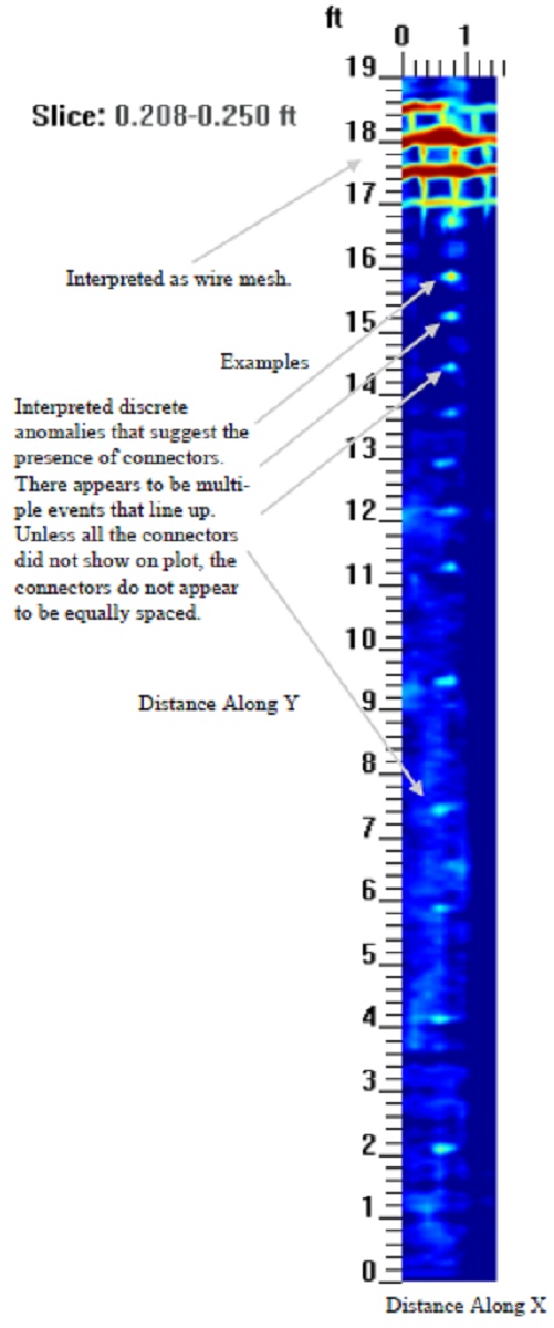
To demonstrate, the adjacent figure, with its field notes, points out bright spots at a depth of about 2.5 to 3 inches (0.208 to 0.250 feet) below the surface. In a similar fashion at other depths, one could see the same bright spots in the plan view representation of the three dimensional results. The bright spots are not equally spaced, which the client pointed out later that they did not expect the decking bolts to be equally spaced. The wire mesh seen at the top of the figure was a welcome sight. Seeing the mesh in the GPR results confirms that additional measures were taken during construction of the concrete floor.
To confirm the location of the decking bolts, with respect to the peaks and troughs of the corrugated steel decking, the adjacent figure presents the GPR scanning results. As shown, the depth is about 5 to 5.5 inches (0.417 to 0.458 feet) below the surface. While other plots also reveal the peaks and valleys of the corrugated metal decking, this plot is a good example of the response. Similarly, to the previous figure, field notes point out the light blue and dark blue patterns. An interpretation indicates the pattern represents the peaks and troughs of the metal decking. Without doubt, the metal decking fasteners appear to line up along a trough.